These are laser engravings were made using a laser cutter and a grayscale engraving technique. The various shades from a black-and-white source file mapped to the laser’s power setting. I developed a way to turn 3D models into depth maps that worked well for this type of engraving. The images show the final engravings and their source files.

Skull 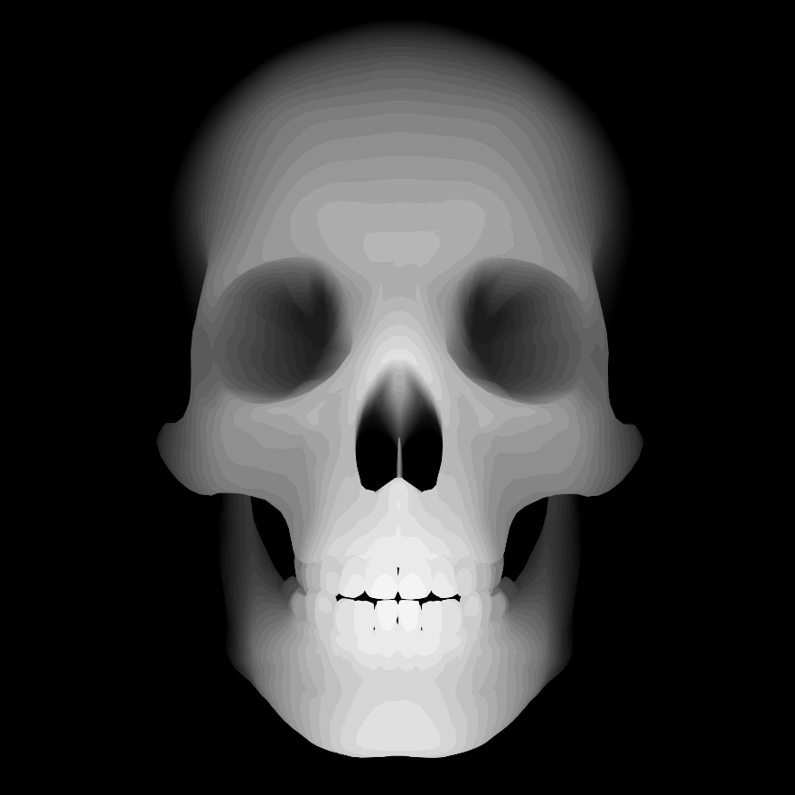
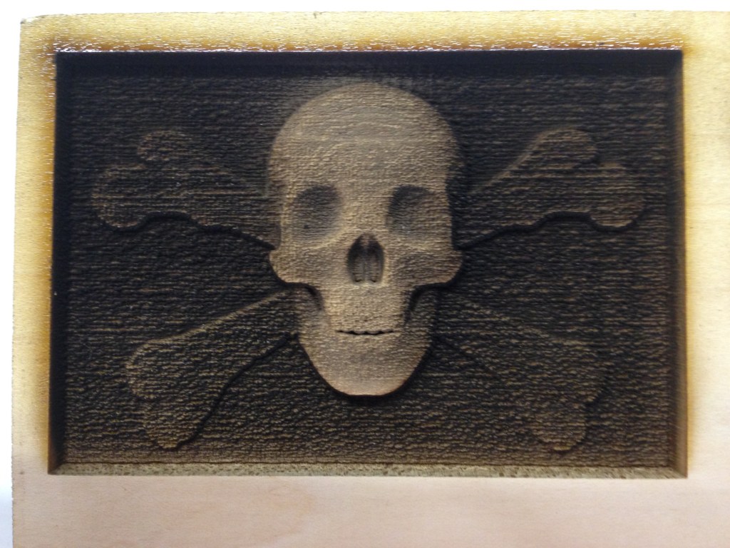
Skull and Crossbones 

Heart 
How to Make Depth Maps in Blender
Below is a short tutorial on creating a depth map using the 3D animation software Blender. There is a bit of a learning curve and the location of some settings might vary depending on your software version, but this should hopefully give a general overview of making a map. You will also need a 3D model (STL files work nicely) to import. I would recommend 3D printing or CAD models from sites like Thingiverse or GrabCAD to get started.
Setting Up the UI
- Change the render mode in the header bar’s drop-down menu from “Blender Render” to “Cycles Render”
- Right click on the main view’s right boundary and select “Split Area”
- Change the editor type on the bottom area from “3D View” to “Node Editor”
Importing Models
- Go to the World tab on the properties editor. Change the surface color to completely black.
- Press [A] to select all the default objects (highlighted objects will be outlined in orange) and then hit [X] to delete them
- Make sure that the cursor is located at the grid’s origin by pressing [Shift][S] and selecting “Cursor to Center”
- Import objects by navigating to File → Import and select the file type for your model
- Models might be too large or too small. You can scale them by pressing [S]
- From the tools sidebar in the main 3D view, select “Smooth” for the shading
Creating the Camera
- Press [Shift][A] and add a camera to the scene
- Rotate around your model until you find an angle you like
- From the 3D view’s menu bar, go to View → Align View → Align Active Camera to View. This sets the camera in the same location as the User view
- Center your model in the camera’s frame. Press [G][Z][Z] to move the camera in and out, [G][X][X] to move it left and right, and [G][Y][Y] to move up and down
Nodes
- Right click your model to select it. In the node editor, click the “New” button and check the “Use Nodes” box
- Press [X] and delete the default nodes
- Press [Shift][A] to add and connect the nodes as shown below. Use the search function in the menu to find the various nodes. For the “Multiply” node, add the “Math” node and change the operation to multiply

- In the 3D view, change the viewport shading from “Solid” to “Rendered”
- If your model is too dark, lower the 0.5 value on the multiply node. If it is too light, increase the value
Advanced: Add and “RGB Curves” node in between the Invert and Emission nodes to change the depth map’s contrast

Rendering
- Once you have a depth map you like, navigate to the Render tab on the properties editor
- Under the Sampling menu, change the render samples from 128 to 500
- At the top menu bar, select Render → Render Image
- To save result once it fully renders, go to Image → Save As Image to save your map to your computer
